TUTORIAL T2c: Modelling and visualization
Provided packages:
- This tutorial will use the following package(s):
- Package urdf_tutorialPackage mastering_ros_robot_description_pkgPackage learning_tf2Package rviz_marker_demo
Download the file modelling_and_visualization_packages.zip and unzip it into your catkin_ws/src folder.
References:
This tutorial is partially based on:
- Chapter 2 of the book Mastering ROS for Robotics Programming from Lentin Joseph.
Robot Modeling
This section is devoted to introduce to the Unified Robot Description Format to model robots in ROS.
The Unified Robot Description Format (URDF) uses XML files to model robots, sensors and the working environment. The URDF package contains a C++ parser for the URDF format.
Using XML tags, the URDF can represent:
- the kinematic description of the robot,
- the dynamic description of the robot,
- the visual representation of the robot, and
- the collision model of the robot.
URDF file have the extension .urdf and are usually stored in the subfolder called urdf of the package folder.
As an extension to URDF, an XML macro language called Xacro has been designed to construct shorter and more readable XML files, as explained in Section Xacro (XML Macros). Xacro files have the extension .xacro.
Main tags
The link tag
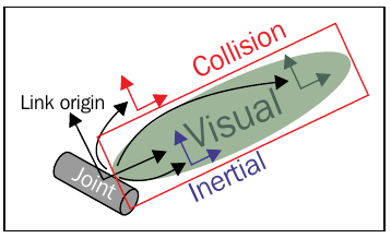
The link tag describes the inertial properties of a single link of a robot (mass and inertia matrix), its visual model (geometry and material) and its collision model (geometry). Each of these elements has its reference frame relative to the link reference frame as shown in the figure below.
<link name="<name of the link>">
  <inertial>...........</inertial>
  <visual> ............</visual>
  <collision>..........</collision>
</link>
The complete description can be found here.
The joint tag
The joint tag describes a robot joint: its type (revolute, continuous, prismatic, fixed, floating, or planar), the links it connects (parent link, child link) and the transform between them (defaulted to the identity), the joint axis (e.g. the axis of rotation for revolute joints), dynamics properties (damping, friction) and limits (joint movement, velocity and effort).
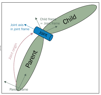
The joint is located at the origin of the child link, as shown in the figure below, and the joint axis is specified in the joint frame.
<joint name="<name of the joint>" type="<type of the joint>">
  <origin ... />
  <parent link="link1"/>
  <child link="link2"/>
  <axis ... />
  <dynamics damping ..../>
  <limit effort .... />
</joint>
The complete description can be found here.
The robot tag
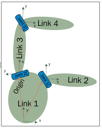
The robot tag describes a complete robot: its name, the links, and the joints. Only tree structures can be represented using URDF, ruling out all parallel robots. The specification assumes the robot consists of rigid links connected by joints; flexible elements are not supported.
<robot name="<name of the robot>"
  <link> ..... </link>
  <link> ...... </link>
  <joint> ....... </joint>
  <joint> ........</joint>
</robot>
A detailed description can be found here.
>>> EXERCISE
 Take a look at the pan_tilt.urdf file that describes a pan-tilt structure (you will find the file in the *urdf* folder in the package *mastering_ros_robot_description_pkg*).
Additional tags
The transmission tag
The transmission tag describes the relationship between an actuator and a joint to model concepts such as gear ratios.
<transmission name="<name of the transmission>"
  <type> .... </type>
  <joint> ... </joint>
  <actuator>... </actuator>
</transmission>
A detailed description can be found here.
The gazebo tag
The gazebo tag is used to add extra information to the links and joints for simulation purposes in the Gazebo simulator.
A detailed description can be found here.
Verification tools
The command line tool check_urdf can be used to verify the correctness of a URDF file. It attempts to parse the file and either prints a description of the resulting kinematic chain, or an error message is reported.
You can test it by checking the correctness of the pan-tilt structure:
$ check_urdf pan_tilt.urdf
Also the tree structure of the robot can be graphically shown using the command tool called urdf_to_graphiz.
$ urdf_to_graphiz pan_tilt.urdf
$ evince pan_tilt.pdf

Xacro (XML Macros)
Xacro is an XML macro language that extends URDF by providing:
- Modularity: It creates macros that can be reused (even in other files), which results in a modular and more readable code.
- Programmability: It supports simple programming statements, which makes the make the description more efficient.
Xacro files modify the robot tag to include a namespace:

Properties
Constants can be declared and used as named values inside the Xacro file, thus allowing to change these values more easily.
<xacro:property name="pan_link_length" value="0.01" />
<xacro:property name="pan_link_radius" value="0.2" />
....
<cylinder length="${pan_link_length}" radius="${pan_link_radius}"/>
Math expressions
Basic operations such as + , -, * , / , unary minus, and parenthesis can be used inside ${}.
<cylinder length="${pan_link_length}" radius="${pan_link_radius+0.02}"/>
Includes
Other Xacro files can be included inside a Xacro file using the xacro:include tag, e.g.:
<xacro:include filename="$(find packageName)/urdf/anotherXacroFile.xacro"/>
Macros
Macros can be defined to allow modularity. They improve the code readability and reduce the number of lines compared to urdf, e.g.:
<xacro:macro name="inertial_matrix" params="mass">
 <inertial>
  <mass value="${mass}" />
  <inertia ixx="0.5" ixy="0.0" ixz="0.0" iyy="0.5" iyz="0.0" izz="0.5" />
 </inertial>
</xacro:macro>
...
<xacro:inertial_matrix mass="1"/>
>>> EXERCISE
 Take a look at the pan_tilt.xacro file that describes a pan-tilt structure.
Conversion from Xacro to urdf
Any Xacro file can be converted to URDF as follows:
$ rosrun xacro xacro pan_tilt.xacro > pan_tilt_generated.urdf
kdl_parser
The Kinematics and Dynamics Library (KDL) defines a tree structure to represent the kinematic and dynamic parameters of a robot mechanism, and provides solvers to compute anything from forward position kinematics, to inverse dynamics.
The kdl_parser provides tools to construct a KDL tree from an XML robot representation in URDF.
The seven DOF arm example

| Joint number | Joint name | Joint type | Limits (deg) |
|---|---|---|---|
| 1 | bottom_joint | Fixed | – |
| 2 | shoulder_pan_joint | Revolute | -150 to 114 |
| 3 | shoulder_pitch_joint | Revolute | -67 to 114 |
| 4 | elbow_roll_joint | Revolute | -150 to 41 |
| 5 | elbow_pitch_joint | Revolute | -92 to 110 |
| 6 | wrist_roll_joint | Revolute | -150 to 150 |
| 7 | wrist_pitch_joint | Revolute | -92 to 113 |
| 8 | gripper_roll_joint | Revolute | -150 to 150 |
| 9 | finger_joint1 | Prismatic | 0 to 25 mm |
| 10 | finger_joint2 | Prismatic | -25 to 0 mm |
>>> EXERCISE
  Take a look at the seven_dof_arm.xacro file, to verify:
  - the use of xacro:property to define constant values,
  - the use of xacro:macro to define the inertial_matrix,
  - the use of xacro:include to include the files describing the sensors,
  - the use of prismatic joints for the fingers
The tf library
This section is devoted to briefly introduce to the transform library, which lets the user keep track over time of multiple coordinate frames and their relationship.
The tf library was designed to be a core library of the ROS ecosystem. It is described in this paper.
tf2 is the second generation of the transform library, which lets the user keep track of multiple coordinate frames over time. The tf2_ros package provides roscpp bindings for tf2.
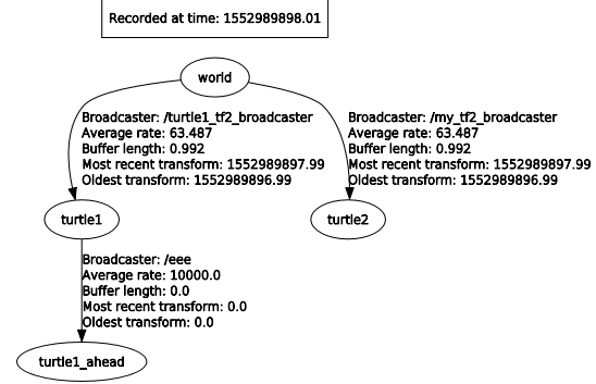
tf2 maintains the relationship between coordinate frames in a tree structure buffered in time (i.e. with transforms as edges and coordinate frames as nodes). It can be visualized using the rqt plugin rqt_tf_tree.
This tree lets the user transform points, vectors, etc between any two coordinate frames at any desired point in time. It can be used to answer questions like:
- Where was the head frame relative to the world frame, 5 seconds ago?
- What is the pose of the object in my gripper relative to my base?
- What is the current pose of the base frame in the map frame?
The nodes may use this package to either listen to or broadcast transforms:
- Listening for transforms - Receive and buffer all coordinate frames that are broadcasted in the system, and query for specific transforms between frames.
- Broadcasting transforms - Send out the relative pose of coordinate frames to the rest of the system. A system can have many broadcasters that each provide information about a different part of the robot.
Coordinate Frame Conventions
Naming: Coordinate frames in ROS are identified by a string frame_id in the format lower case underscore separated. This string has to be unique in the system. All data produced can simply identify it’s frame_id to state where it is in the world. frame_ids do not follow namespace remapping rules
TransformStamped message
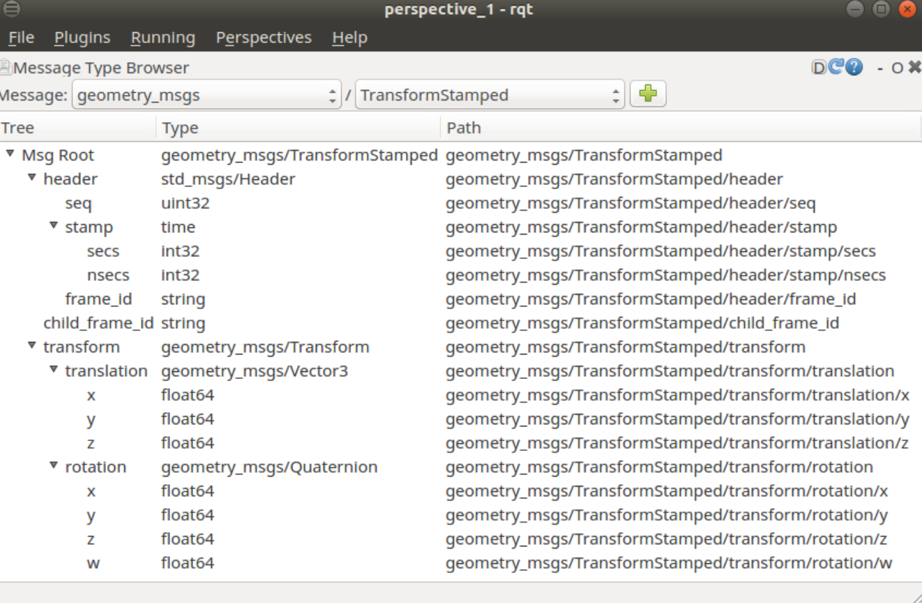
The message data type for the transforms with time information is the geometry_msgs/TransformStamped:
The tf2::Transform
The tf2::Transform class allows to define a transform:
- The orientation is defined as a tf2:Quaternion.
- The position defined as a Vector3.
1 2 3 4 | tf2::Quaternion q;
q.setRPY(1.570796327,0,0); //R: roll angle around x-axis, P: pitch angle around y-axis, Y: yaw angle around z-axis
tf2::Vector3 c(0,0.1,0);//x,y,z
tf2::Transform mytransform(q,c);
|
The composition of transforms can be done using the multiply operator.
Conversions
The convert function is a tf2 function that allows you to convert between data types, in particular between geometry_msgs::TransformStamped and tf2::Stamped<tf2::Transform>:
1 2 3 | geometry_msgs::TransformStamped transformStamped;
tf2::Stamped<tf2::Transform> tfs;
tf2::convert(transformStamped, tfs);
|
To create a geometry_msgs::TransformStamped from a tf2::Transform we need to add the header information (time stamp and parent frame id), the frame id, and fill the orientation and position, e.g. to create it from the tf2::Transform called mytransform defined above:
1 2 3 4 5 6 7 8 9 10 11 | geometry_msgs::TransformStamped transformStamped;
transformStamped.header.stamp = ros::Time::now();
transformStamped.header.frame_id = "world";
transformStamped.child_frame_id = "mytransform_id";
transformStamped.transform.translation.x = mytransform.getOrigin().getX();
transformStamped.transform.translation.y = mytransform.getOrigin().getY();
transformStamped.transform.translation.z = mytransform.getOrigin().getZ();
transformStamped.transform.rotation.x = mytransform.getRotation().getX();
transformStamped.transform.rotation.y = mytransform.getRotation().getY();
transformStamped.transform.rotation.z = mytransform.getRotation().getZ();
transformStamped.transform.rotation.w = mytransform.getRotation().getW();
|
tf Broadcasters
Static Transform broadcasters
tf2_ros provides an executable named static_transform_publisher to broadcast static transforms:
static_transform_publisher x y z yaw pitch roll frame_id child_frame_id
Publishes a static coordinate transform to tf2 using an x/y/z offset in meters and yaw/pitch/roll in radians. (yaw is rotation about Z, pitch is rotation about Y, and roll is rotation about X).
static_transform_publisher x y z qx qy qz qw frame_id child_frame_id
Publishes a static coordinate transform to tf2 using an x/y/z offset in meters and quaternion.
It can be used either as a commandline tool or as a node that you can add to your launch files (where you set a given node name):
$ rosrun tf2_ros static_transform_publisher 1 0 0 0 0 0 1 turtle1 turtle1_ahead
<launch>
   <node pkg="tf2_ros" type="static_transform_publisher" name="tool_broadcaster" args="1 0 0 0 0 0 1 turtle1 turtle1_ahead" />
</launch>
Writing a tf2 broadcaster
The class TransformBroadcaster has been designed to send transformations over the wire.
The file turtle_tf2_broadcaster.cpp creates a node that subscribes to the pose of a turtle, whose name has been passed as a parameter, and broadcasts this pose as a transform (additionally, a static transform corresponding to a translation along the x axis w.r.t the turtle pose has been set in the launch file).
1 2 3 4 5 6 7 8 9 10 11 12 13 14 15 16 17 18 19 20 21 22 23 24 25 26 27 28 29 30 31 32 33 34 35 36 37 38 39 40 41 42 43 44 45 46 47 48 | #include <ros/ros.h>
#include <tf2/LinearMath/Quaternion.h>
#include <tf2_ros/transform_broadcaster.h>
#include <geometry_msgs/TransformStamped.h>
#include <turtlesim/Pose.h>
std::string turtle_name;
void poseCallback(const turtlesim::PoseConstPtr& msg){
static tf2_ros::TransformBroadcaster br;
geometry_msgs::TransformStamped transformStamped;
transformStamped.header.stamp = ros::Time::now();
transformStamped.header.frame_id = "world";
transformStamped.child_frame_id = turtle_name;
transformStamped.transform.translation.x = msg->x;
transformStamped.transform.translation.y = msg->y;
transformStamped.transform.translation.z = 0.0;
tf2::Quaternion q;
q.setRPY(0, 0, msg->theta);
transformStamped.transform.rotation.x = q.x();
transformStamped.transform.rotation.y = q.y();
transformStamped.transform.rotation.z = q.z();
transformStamped.transform.rotation.w = q.w();
br.sendTransform(transformStamped);
}
int main(int argc, char** argv){
ros::init(argc, argv, "my_tf2_broadcaster");
ros::NodeHandle private_node("~");
if (! private_node.hasParam("turtle"))
{
if (argc != 2){ROS_ERROR("need turtle name as argument"); return -1;};
turtle_name = argv[1];
}
else
{
private_node.getParam("turtle", turtle_name);
}
ros::NodeHandle node;
ros::Subscriber sub = node.subscribe(turtle_name+"/pose", 10, &poseCallback);
ros::spin();
return 0;
};
|
Build the learning_tf2 package and launch the nodes:
$ catkin build learning_tf2
$ source devel/setup.bash
$ roslaunch learning_tf2 start_demo.launch
You can visualize the tf tree with rqt:
$ rqt -s rqt_tf_tree
Move the turtle with the keys and verify the broadcasted transforms with the tf_echo utility:
$ rosrun tf tf_echo /world /turtle1
$ rosrun tf tf_echo /world /turtle1_ahead
>>> EXERCISE
  - Add a second turtle using the /spawn service. Call it 'turtle2'.
  - Run the node turtle_tf2_broadcaster with the name of the turtle as an argument (i.e. $ rosrun turtle_tf2 turtle_tf2_broadcaster turtle2).
  - Use tf_echo to visualize the transform that locates 'turtle2'.
  - Update the visualization of the tree in the rqt tool.
tf listeners
The class TransformListener has been designed to receive the transforms information, to store it, and later use it to respond to queries about the resultant transforms between different coordinate frames.
The file turtle_tf2_listener.cpp creates a node that spawns a second turtle and then computes a velocity to drive the second turtle towards the first one. This is done by computing the transform between the transforms broadcasted by the turtles.
1 2 3 4 5 6 7 8 9 10 11 12 13 14 15 16 17 18 19 20 21 22 23 24 25 26 27 28 29 30 31 32 33 34 35 36 37 38 39 40 41 42 43 44 45 46 47 48 49 50 51 52 | #include <ros/ros.h>
#include <tf2_ros/transform_listener.h>
#include <geometry_msgs/TransformStamped.h>
#include <geometry_msgs/Twist.h>
#include <turtlesim/Spawn.h>
int main(int argc, char** argv){
ros::init(argc, argv, "my_tf2_listener");
ros::NodeHandle node;
ros::service::waitForService("spawn");
ros::ServiceClient spawner =
node.serviceClient<turtlesim::Spawn>("spawn");
turtlesim::Spawn turtle;
turtle.request.x = 4;
turtle.request.y = 2;
turtle.request.theta = 0;
turtle.request.name = "turtle2";
spawner.call(turtle);
ros::Publisher turtle_vel =
node.advertise<geometry_msgs::Twist>("turtle2/cmd_vel", 10);
tf2_ros::Buffer tfBuffer;
tf2_ros::TransformListener tfListener(tfBuffer);
ros::Rate rate(10.0);
while (node.ok()){
geometry_msgs::TransformStamped transformStamped;
try{
transformStamped = tfBuffer.lookupTransform("turtle2", "turtle1",
ros::Time(0));
}
catch (tf2::TransformException &ex) {
ROS_WARN("%s",ex.what());
ros::Duration(1.0).sleep();
continue;
}
geometry_msgs::Twist vel_msg;
vel_msg.angular.z = 4.0 * atan2(transformStamped.transform.translation.y,
transformStamped.transform.translation.x);
vel_msg.linear.x = 0.5 * sqrt(pow(transformStamped.transform.translation.x, 2) +
pow(transformStamped.transform.translation.y, 2));
turtle_vel.publish(vel_msg);
rate.sleep();
}
return 0;
};
|
The launch file start_demo_2.launch runs one broadcaster node per turtle, the listener node and the turtlesim and teleope_key nodes. By launching all of them you can see how, while teleoperating turtle1, turtle2 follows turtle1.
$ roslaunch learning_tf2 start_demo_2.launch
You can visualize the tf tree with rqt, and monitorize the error using tf_echo:
$ rosrun tf tf_echo /turtle1 /turtle2
The rviz visualization tool
Rviz is a 3D visualization tool for ROS (http://wiki.ros.org/rviz).
Launching rviz
We can use rviz to visualize the robots in the mastering_ros_robot_description_pkg package.
Build the package and launch the following launch file, that contains a node to run the rviz.
<?xml version="1.0"?>
<launch>
 <arg name="model" />
 <param name="robot_description" textfile="$(find mastering_ros_robot_description_pkg)/urdf/pan_tilt.urdf" />

 <node name="joint_state_publisher_gui" pkg="joint_state_publisher_gui" type="joint_state_publisher_gui" />
 <node name="robot_state_publisher" pkg="robot_state_publisher" type="robot_state_publisher" />
 <node name="rviz" pkg="rviz" type="rviz" args="-d $(find mastering_ros_robot_description_pkg)/urdf.rviz" required="true" />
</launch>
$ catkin build mastering_ros_robot_description_pkg
$ source devel/setup.bash
$ roslaunch mastering_ros_robot_description_pkg view_demo.launch

!!!!! Troubleshooting: If the pan-tilt structure is not visualized see The ~/.bashrc file.
>>> EXERCISE
 Repeat for the 7 DOF arm using the view_arm.launch file, that loads the robot_description parameter with the robot model read from the seven_dof_arm.xacro file.
These launch files also run two nodes:
- the joint_state_publisher,
- the robot_state_publisher,
which are explained next.
joint_state_publisher
The joint state publisher is one of the ROS packages that is commonly used to interact with each joint of the robot. The package contains the joint_state_publisher_gui node, which will find the non-fixed joints from the URDF model and publish the joint state values of each joint in the sensor_msgs/JointState message format, according to the sliders shown in the GUI.
robot_state_publisher
The robot state publisher package is used to publish the state of the robot to tf. i.e. this package subscribes to joint states of the robot and publishes the 3D pose of each link using the kinematic representation from the URDF model.
Markers
Rviz provides the Marker Display to let you visualize data without rviz knowing anything about interpreting that data. Data is sent to the display by publishing visualization_msgs/Marker messages, which let you show objects (3D meshes) or basic shapes (boxes, spheres, lines, arrows,..). The set of types that can be dispayed is available here.
The visualization_msgs/MarkerArray message type describes a vector of visualization_msgs/Marker messages, which have the following fields:

As an example, build and run the rviz_marker_demo package:
$ catkin build rviz_marker_demo
$ roslaunch rviz_marker_demo rviz_marker_demo.launch

>>> EXERCISE
    Take a look at the rviz_node.cpp file that implements a node that publishes marker messages to place objects on the scene.
The following issue should be noted:
- In this example, objects are located w.r.t a frame called /assembly_frame, i.e. when they are published, the field marker.header.frame_id is set to /assembly_frame. Then, the launch file runs a static_transform_publisher to broadcast a fixed transform between the global frame map and the example reference frame /assembly_frame.
The rviz GUI
The rviz GUI can be configured by adding (using the Add button on the bottom left) what should be visualized, e.g. in the example above two Displays (the Marker and the Axes).
The configuration of the GUI is stored in a file (with the File->Save Config As menu), e.g. in the previous example it was the file rviz_marker_demo.rviz, and then in the launch file this file can be passed as an argument to the rviz node, such that when rviz is run it opens with the desired appearance.
See the rviz user guide for more details.
EXERCISE 4
In the ur3_demo_package there is a launch file prepared to broadcast a transform called aruco_201 that locates pawn number 201 w.r.t. the world reference frame:
$ roslaunch ur3_demo_package demo_services_tf.launch
Besides visualizing it in rviz, take a look at the tf_tree and echo its values:
$ rqt -s rqt_tf_tree
$ rosrun tf tf_echo /world /aruco_201
- Implement a node called grasp_broadcaster that:
- Defines a tf2_ros::TransformBroadcaster and broadcasts a geometry_msgs::TransformStamped with a grasp configuration defined w.r.t. the aruco_201 frame. Call it grasp01.
- Defines a tf2_ros::TransformBroadcaster and broadcasts a geometry_msgs::TransformStamped with the object frame defined w.r.t. the aruco_201 frame. Call it pawn_201. Frame pawn_201 should have the z-axis pointing up and be located at the center of the object.
- Implement a node called grasp_listener that:
- Uses a tf2_ros::TransformListener to get the transform grasp01 w.r.t. the base of the robot (frame team_A_base_link) and prints the transform.
- Uses a tf2_ros::TransformListener to get the transform pawn_201 w.r.t. the world and prints the transform.
TEMPLATE: You can use the template of package ris_solution found here.