Robot modelling
Based on Section 2.8 of Robotics: Modelling, Planning and Control.
Link to the practical session on Robot Modelling
Denavit - Hartenberg Convention
Manipulator = series of links (rigid bodies) connected by joints (essentially prismatic or revolute), forming a kinematic chain, between the base and the end-effector.
The Denavit-Hartenberg convention is a method to derive the relative pose of two consecutive links of a kinematic chain, and is used to obtain a kinematic model of the manipulator.
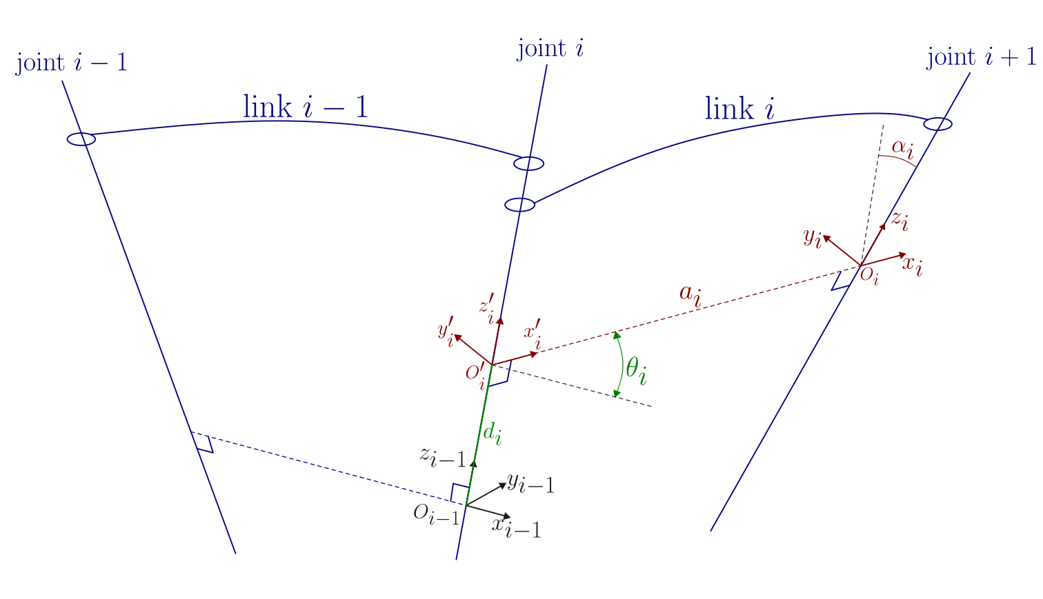
Definition of frames
The frame \(i\) that describes the pose of link \(i\) is defined as follows:
\(z_i\) axis: along joint \(i+1\).
Origin \(O_i\) : at the intersection of \(z_i\) and the common normal to \(z_i, z_{i-1}\).
\(x_i\) axis: along the common normal between \(z\) axis, from joint \(\: i\) towards joint \(i+1\), i.e., from \(z_{i-1}\) to \(z_{i}\).
\(y_i\) axis: defined such that the frame is right-handed.
There are some special cases where the definitions are non-unique (choices are proposed to simplify the procedures).
Frame \(0: O_0\) and \(x_0\) are arbitrarily chosen, they may be set coincident with the manipulator base frame.
Frame \(n: z_n\) is not uniquely defined; it is usually chosen aligned with \(z_{n-1}\).
Two consecutive axes are parallel: there are infinite common normals, one of them is arbitrarily chose, usually the one that makes the \(d\) parameter to be zero (see below).
Two consecutive axes intersect: the sense of \(x_i\) is arbitrarily chosen, if possible in the same sense as \(x_{i-1}\).
Joint \(i\) is prismatic: the sense of \(z_{i-1}\) is arbitrarily chosen.
Definition of the transformation between frames
Then, according to the frames defined previously, the following parameters are introduced to define the transformation between link reference frames:
\(a_i\): distance between \(O_i'\) and \(O_i\)
\(d_i\): distance between \(O_{i-1}\) and \(O_i'\)
\(\alpha_i\): angle between \(z_{i-1}\) and \(z_i\) (positive = counter-clockwise)
\(\theta_i\): angle between \(x_{i-1}\) and \(x_i\) about \(z_{i-1}\) axis
Note that:
\(a_i, \alpha_i\) = constant values always, depend on the geometry only.
\(\theta_i\) = variable for revolute joints.
\(d_i\) = variable for prismatic joints.
Finally, the transformation between frames is computed through the intermediate frame \(O_i'\!\!-\!x_i'\,y_i'\,z_i'\):
Procedure
The following procedure should be followed to determine the DH parameters of a manipulator:
Intitialize:
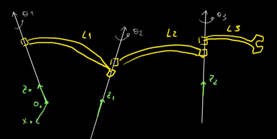
Find and number consecutively the joint axes: \(z_0, ... z_{n-1}\)
Choose frame 0 by locating the origin on \(z_0\); choose \(x_0\) arbitrarily (make it coincident with that of the base frame, if possible) and select \(y_0\) in order to have a right-handed frame.
Iterate: Repeat steps 3 to 5 for \(i=1\) to \(n-1\).
Locate \(O_i\) at the intersection of \(z_i\) with the common normal \((z_{i-1},z_i)\).
However, if \(z_{i-1}\) and \(z_i\) are parallel:
\[\begin{split}\begin{cases} \text{locate } O_i \text{ such that } d_i = 0 \text{ (when joint is revolute),}\\ \text{locate } O_i \text{ at the mechanical limit of the joint (when joint is prismatic).} \end{cases}\end{split}\]
Choose \(x_i\) along the common normal \((z_{i-1},z_i)\) from \(z_{i-1}\) to \(z_i\).
Choose \(y_i\) to be right-handed.
Finalize:
Choose Frame \(n\) such that:
Write table of parameters \(a_i, d_i, \alpha_i, \theta_i\).
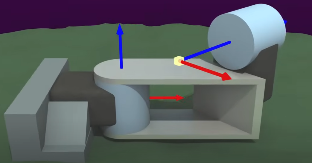
The following videos summarize the reference frames used for the definition of the DH parameters used to model robotic manipulators:
Modified Denavit - Hartenberg Convention
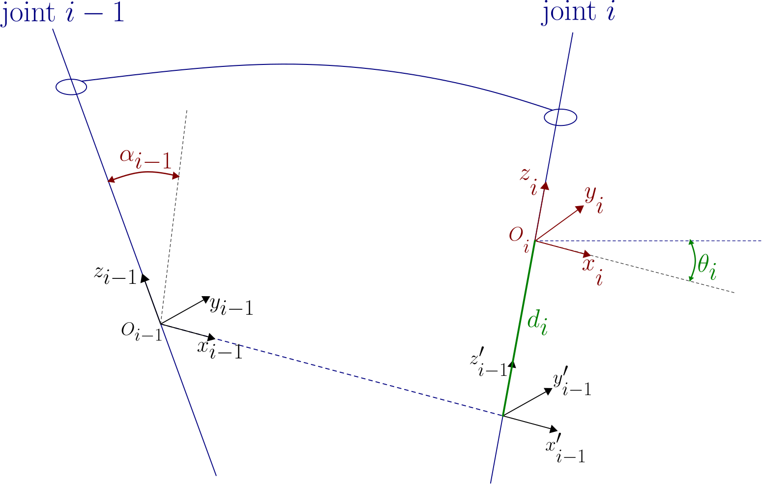
This is a variant of the DH parameters, introduced by Craig in 1986, that choses \(z_i\) to be along joint \(i\) axis:
Unified Robotic Description Format (URDF)
This is an alternative way to model kinematic manipulators. It provides a flexible method to define the transformations between links using six degrees of freedom.
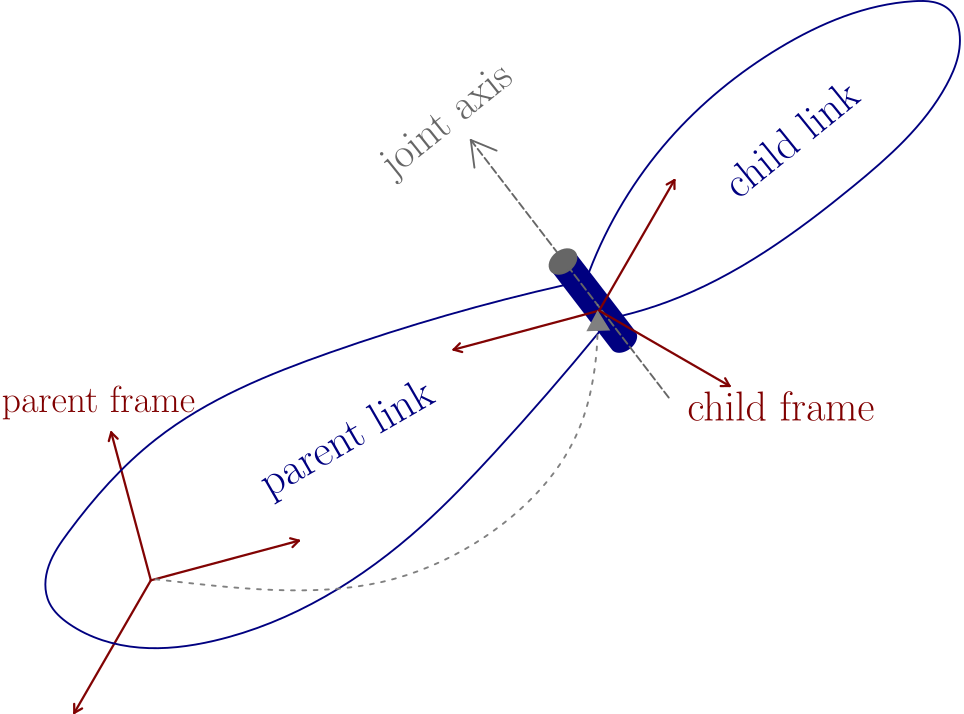
origin = Transformation that locates the child link w.r.t the parent link.
axis = joint-axis expressed in the child frame (defaults to \([1\;0\;0]^{T}\) ).
Examples
In the Direct Kinematics section (2.1) we will derive the DH parameters of:
the three-link planar arm
the spherical arm
the anthropomorphic arm
the spherical wrist