Overview
What is The Kautham Project?
The Kautham Project is a software tool developed at the Service and Industrial Robotics (SIR) group of the Institute of Industrial and Control Engineering (IOC) of the Universitat Politècnica de Catalunya (UPC), for teaching and research in robot motion planning.
The tool allows to cope with problems with one or more robots, being a generic robot defined as a kinematic tree with a mobile base, i.e. the tool can plan and simulate from simple two degrees of freedom free-flying robots to multi-robot scenarios with mobile manipulators equipped with anthropomorphic hands. The main core of planners is provided by the Open Motion Planning Library (OMPL).
Different basic planners can be flexibly used and parameterized, allowing students to gain insight into the different planning algorithms. Among the advanced features the tool allows to easily define the coupling between degrees of freedom, the dynamic simulation and the integration with task planners. It is principally being used in the research of motion planning strategies for dexterous dual arm robotic systems.
Objective
The objective of this software is to provide an environment for testing and developing motion planning algorithms.
Teaching perspective: Allow students to easily gain insight into the different planning algorithms.
Availability of a wide range of planners,
Possibility to flexibly use and parameterize planners
Capacity to visualize 2D and 3D configuration spaces, as well, as projections of higher-dimensional configuration spaces.
The following figure shows simple 2D or 3D examples of free-flying robots or simple manipulators.

Research perspective: Ease the development of motion planning strategies for complex robotic systems.
Simple configurability of the coupling between degrees of freedom
Benchmarking capabilities
Dynamic simulation
ROS interface to be easily integrated into robotic developments
The following videos show examples of human-like motion planning for grasping operations of hand-arm systems:
Tools used and basic features
Uses OMPL suite of planners (geometric and control-based)
Uses Coin3D for visualization
Uses ODE physics engine
Robot models are defined using URDF
Describes robots as kinematic trees with a mobile base (SE3xRn configuration space)
Geometry is described in VRML files (if the ASSIMP package is available, many other formats like DAE or STL are also supported).
Allows multi-robot systems
Allows the coupling of degrees of freedom
Offers a ROS interface as a set of services.
External Documentation
If you use Kautham in a publication, please cite it as:
@inproceedings{kautham2014,
author = {Jan Rosell and
            Alexander P\'erez and
            Akbari Aliakbar and
            Muhayyuddin and
            Leopold Palomo and
            N\'estor Garc\'{\i}a},
title = {The Kautham Project: A teaching and research tool for robot motion planning},
booktitle={Proc. of the IEEE Int. Conf. on Emerging Technologies and Factory Automation, ETFA'14},
year = {2014},
url = {sir.upc.edu/kautham}
}
Main Features
Problem description
Problems are described with simple XML files that contain four basic main sections:
Robot: it contains the file with the description of the robot kinematics and geometry (see Modeling robots and obstacles) and the following subtags:
Limits: the workspace limits (required for the case of a robot with a mobile base; if not provided the robot will be considered fixed),
Home: the position and orientation of the robot (required for the case of a robot with a fixed base), with the orientation described in axis-angle form,
Weights: values to weigh the translational and rotational distances in case of mobile base (optional, values defaulted to 1, see the TX90_R6_mobileBase demo for an example).
InvKinematic: label of the inverse kinematic to be used (optional, see the TX90_Hand_PMDs demo for an example ).
ViewLink: name of the link whose path will be drawn if a solution is found (optional, defaulted to the last link of the trunk in the kinematic tree-structure, see the Tiago_kitchen demo for an example).
Several robots can be included; they are labeled with numerical tags starting at 0 according to the order in the problem file.
Obstacle: it contains the file with the description of the obstacle geometry (see Modeling robots and obstacles) and the following subtag:
Limits: the workspace limits (required for the case when the obstacle pose shall be modified, like in the OMPL_RRTconnect_boxes_world_R2 example; not provided when obstacles are considered fixed, which is the usual case),
Home: the pose (with the orientation described in axis-angle form).
Several obstacles can be included; they are referenced using their name specified in the URDF file.
Controls: it contains the file describing how the degrees of freedom of the robot(s) are actuated (see Moving the robot joints). If not included, the default set of controls (each one moving a degree of freedom) is considered.
Control files for obstacle(s) can be added (using the argument obstacle instead of robot) so as to allow to change the obstacle poses (using the GUI or the corresponding ROS service). See the file OMPL_RRTConnect_boxes_world_R2.xml in the boxes_world_R2 demo.
Planner: it contains two subtags:
Parameters: that includes the planner name (see The planners) to solve the query and the values of the planner parameters (if the default values are to be used they need not be listed),
Queries: the queries to be solved, although currently only a single query is processed, it is set with the initial and goal configurations defined as a vector of controls (size depending on the control file used).
Several examples are provided in the demos folder (see The directory structure).
1 2 3 4 5 6 7 8 9 10 11 12 13 14 15 16 17 18 19 20 21 22 23 24 25 26 27 28 29 30 31 | <?xml version="1.0"?>
<Problem name="OMPL_PRM_Staubli_R6_mobileBase_two_columns">
<Robot robot="robots/tx90_mobile.urdf" scale="1.0">
<Limits name="X" min="-0.4" max="1.2" />
<Limits name="Y" min="-0.2" max="1.0" />
<Limits name="Z" min="0.0" max="1.0" />
<Home TH="3.1415926536" WZ="1.0" WY="0.0" WX="0.0" Z="0.0" Y="0.4" X="-0.3"/>
<WeightSE3 rho_t="10.0" rho_r="1.0" />
</Robot>
<Obstacle obstacle="obstacles/columns.urdf" scale="0.018">
<Home TH="0.0" WZ="0.0" WY="0.0" WX="1.0" Z="0.0" Y="0.0" X="0.25" />
</Obstacle>
<Controls robot="controls/TX90_mobile.cntr" />
<Planner>
<Parameters>
<Name>omplPRM</Name>
<Parameter name="Max Planning Time">60.0</Parameter>
<Parameter name="BounceDistanceThreshold">0.5</Parameter>
<Parameter name="Speed Factor">1</Parameter>
<Parameter name="MaxNearestNeighbors">10</Parameter>
<Parameter name="DistanceThreshold">1</Parameter>
<Parameter name="Sampler 0(r) 1(h) 2(sdk) 3(g)">3</Parameter>
</Parameters>
<Queries>
<Query>
<Init>0.15 0.68 0.64 0.62 0.75 0.69 0.27 0.28</Init>
<Goal>0.79 0.91 0.11 0.49 0.87 0.73 0.25 0.75</Goal>
</Query>
</Queries>
</Planner>
</Problem>
|
Modeling robots and obstacles
Robot and obstacle models are stored in the models folder inside the demos folder (see The directory structure), although other locations can be used by setting the models path using the GUI (see How to set the path of the model folder?).
Robots are modeled using the Universal Robotic Description Language (URDF), which include the files describing the geometry of the rendering models and (optionally) the collision models.
The native geometry format in Kautham is VRML and if the ASSIMP package is available in the system, many other formats like DAE or STL are also supported.
Some of the available robots found at the models/robots folder are:
UR3 and UR5 from Universal Robots
Tx90 from Stäubli
Tiago from PAL robotics
Yumi from ABB
Allegro mechanical hand
Robotiq gripper
Rigid objects as free-flying robots
Obstacles are also modelled using URDF files.
Some available obstacles found at the models/obstacles folder are:
a kitchen environment
all the parts of a Battat toy plane
a chessboard and the chess pieces
several simple objects
The planners
Potential field-based planners: Two planners are provided, one based on the navigation function NF1 and the other one based on harmonic functions. Although coded for n dimensions, these planners work correctly for  since they are based on a grid decomposition of the configuration space.
Sampling-based planners: The sampling-base planners provided by Kautham come from OMPL. They are divided into:
Geometric planners: Planners that only account for the geometric and kinematic constraints of the system (it is assumed that any feasible path can be turned into a dynamically feasible trajectory).
Some geometric planners from OMPL are currently available (PRM, RRT, RRT-Connect, RRT*, SBL, EST, and KPIECE); other OMPL planners can easily be incorporated.
Control-based planners: Planners designed for systems subject to differential constraints (these planners rely on state propagation rather than simple interpolation to generate motions).
Differential constraints for a dual-drive, a car and a plane are available, with the RTT and SST planners.
Physics-based planners: These are planners that use the Open Dynamics Engine as state propagation, conceived to take into account dynamic interactions.
Examples with a free-flying robot, a car-like robot and a 2D manipulator are provided that use the KPIECE planner.
Moving the robot joints
The configuration space of a problem with  robots is the composition of the configuration spaces
  :
:

where  since robots are considered as tree-like kinematic structures with
  joints and a mobile base (although the mobile base is optional and also the case of
  is possible).
Configurations in  are represented by vectors of dimension
  ,
with each component normalized in the range
,
with each component normalized in the range ![[0,1]](../../_images/math/a7b17d1c3442224393b5a845ae344dbe542593d7.png) , i.e.:
, i.e.:
The  degrees of freedom of the robotic system can be actuated either separately or in a coupled way.
To model this, the following expression is used to determine a configuration  using a vector of
  controls,
  , a
, a  mapping matrix,
  , and a vector of offsets,
  :
:
By default, each degree of freedom is actuated separately, i.e. one control is created per each non-fixed joint and, if the problem definition file includes the workspace limits thus indicating that the base is mobile, then six more controls are added for the mobile base (three for translations and three for orientations).
This mode can be overridden by defining the XML control file with the controls to be used, like:
Set of controls to move the joints of the Tiago arm and torso, plus another control to move simultaneously the two fingers of the gripper (no controls to move the base are provided):
Set of controls to move the base of the Tiago robot, keeping the arm and torso at a fixed configuration.
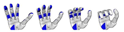
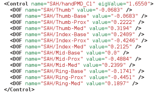
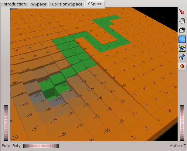
The following figure shows the control that allows to move simultaneously all the joints of a mechanical hand, following a given hand synergy (the values correspond to the columns of matrix K that determines the coupling between the d.o.f.):
Comments
The offset values need not be explicitly specified, since a default value of 0.5 is set.
Note that the offset values of the joints that are not actuated (i.e. that are not involved in any control) are used to fix the robot at a given configuration. If there are no controls actuating the degrees of freedom of the base, these offset values are used to fix the robot in the workspace, provided the Limits are set in the problem file (being this an alternative way that overrides the Home pose specification).
The controls for the rotational degrees of freedom are X1, X2 and X3, which are the variables used to parameterize a quaternion as explained in this paper. These controls are not intuitive, like Euler angles can be, but allow to uniformly sample SO(3) in a correct way.
The GUI
The Graphical User interface is the following:
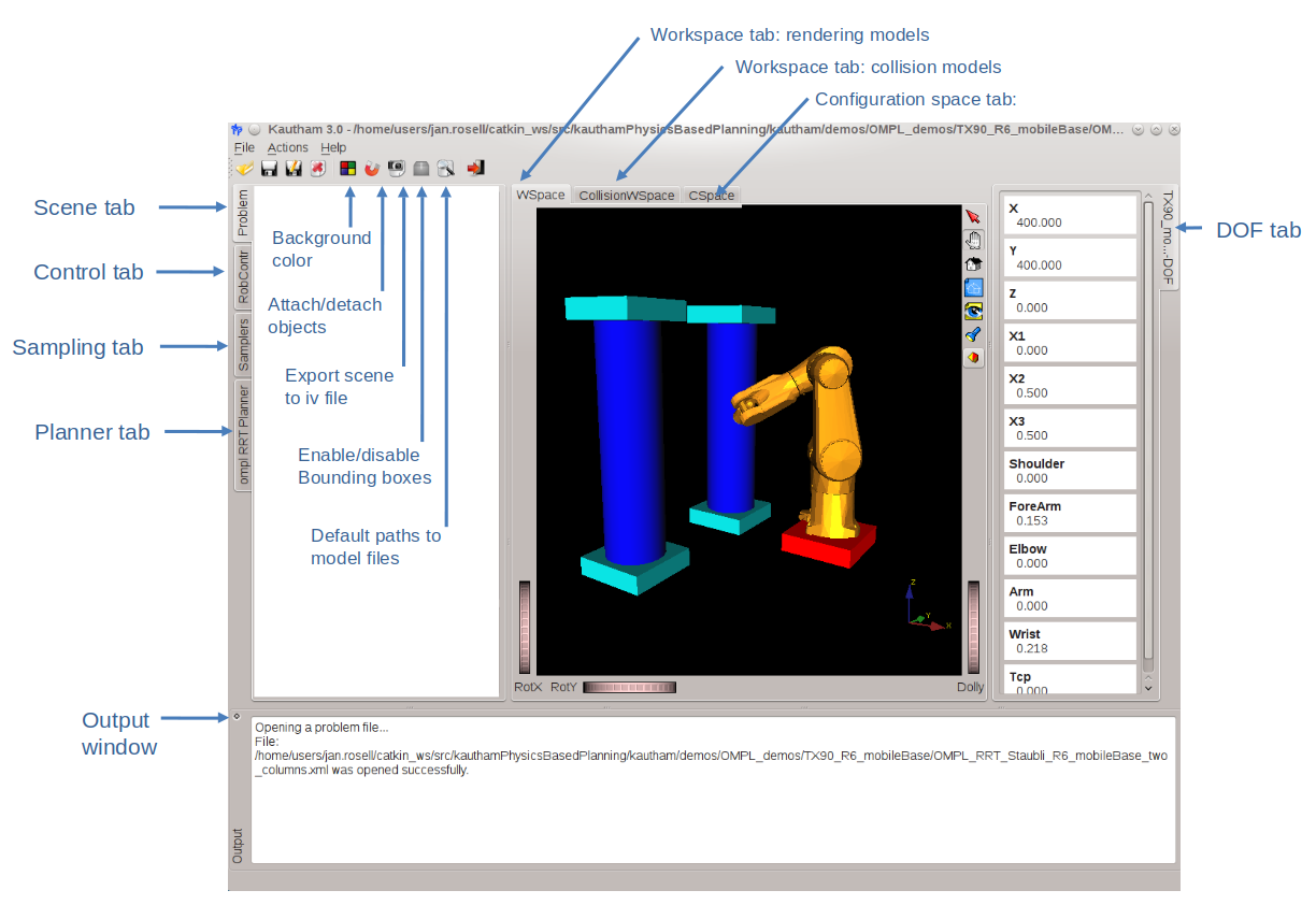
The main interaction tabs are:
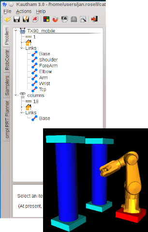
Problem tab: Describes the robots and obstacles in the scene.
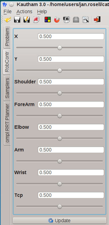
Control tab: Allows to move the robot. In this example each DOF is independently actuated by a single control. Recall that controls are defined in the range [0,1].
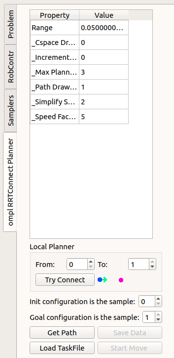
Planner tab: Used to set the planner parameters, launch a query (with the GetPath button) and visualize the solution (with the Start Move button) if available. Also, the Local Planner part allows to test the rectilinear path in Cspace between two samples.
If a solution is found it can be stored in an XML file (using the Save Data button) and reproduced later (with the Load Taskfile button).
The parameters that can be set are the following:
General parameters involved in any planner used (although some of them are only available for geometric planners):
_Cspace Drawn: To select the robot configuration space, if there is more than one. Default is 0._Incremental (0/1): To reuse previous planner data (1) or not (0)._Max Planning Time: To define the maximum allowed planning time (not considering the simplification of the solution)._Path Drawn (0/1): To select whether the path followed by the TCP is drawn or not._Simplify Solution: To select the simplification method (0 no simplification, 1 rounding, 2 shorten)._Speed Factor: Increases the speed of the motion along the solution path. Default set to 1.
Planner-dependent parameters:
e.g. Range for an RRTConnect planner
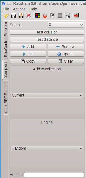
Sampling tab: Used to visualize the sample set of a given planner, or to generate a sample set and to test for collision or distance.
The visualization tabs are:
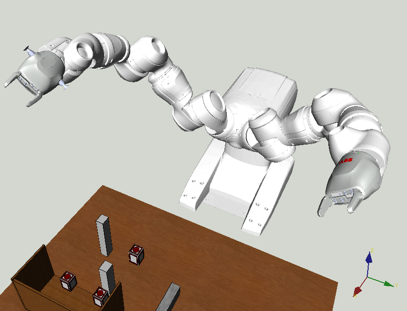
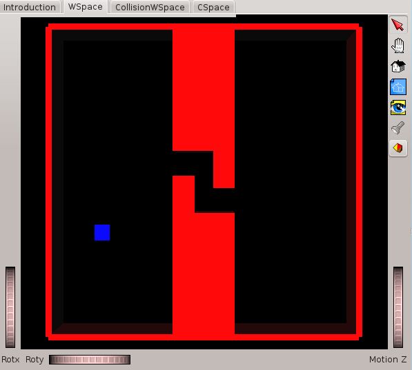
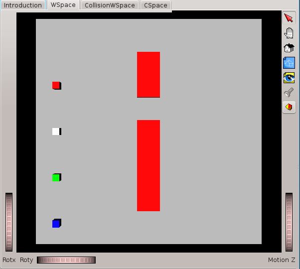
WSpace: To visualize the scene (the robots and the obstacles). The translational solution trajectories of the end-effectors are also shown if the parameter _Path Drawn (0/1) is set to 1.
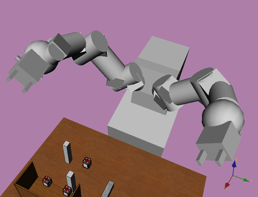
CollisionWSpace: To visualize the models of the robots and obstacles used for collision-checking (if no collision models are provided, then it shows the same as the WSpace tab). If the parameter _Path Drawn (0/1) is set to 1, this tab also shows the translational solution trajectories of the end-effectors and their position for the configurations of the planner data structure (roadmap or tree).
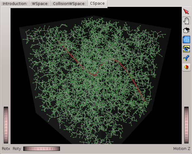
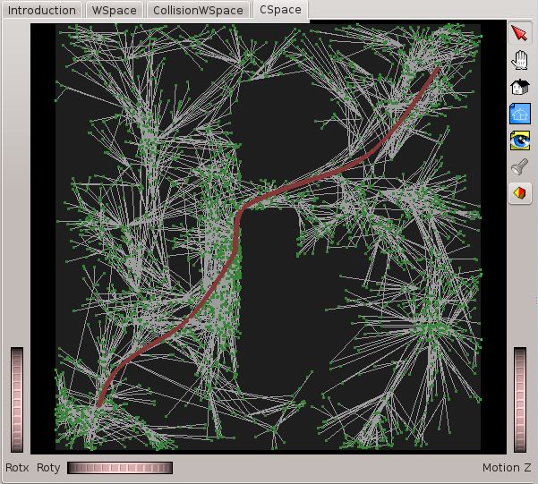
CSpace: For 2- or 3-dimensional problems the roadmaps, trees or potential landscapes can be visualized.
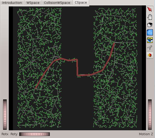
For higher dimensional problems, the projections of the configuration space onto the first two or three degrees of freedom of each robot are visualized. As an example, the six-dimensional configuration space of a free-flying L-shaped robot are projected onto the translational degrees of freedom subspace, and the eight-dimensional configuration space of 4 mobile planar robots moving in x and y, that is projected onto the two-dimensional subspace corresponding to robot 1.

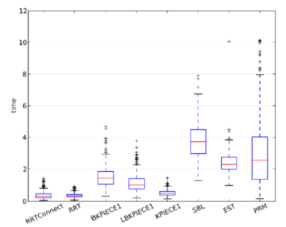
Benchmarking
A console application, called kautham-console, is provided to run in batch mode and execute different benchmarkings, making use of the OMPL benchmarking utility.
It solves a motion planning problem repeatedly with different planners, different samplers, or even differently configured versions of the same planning algorithm. The benchmarking is configured with an XML file, like the following, that specifies the problem files and the general benchmarking parameters.
1 2 3 4 5 6 7 8 9 10 11 | <Benchmark Name="experiment">
<Problem File="OMPL_PRM_bigcube-s-passage_R2.xml" PlannerAlias="PRMrnd"/>
<Problem File="OMPL_PRMhalton_bigcube-s-passage_R2.xml" PlannerAlias="PRMhal"/>
<Problem File="OMPL_PRMsdk_bigcube-s-passage_R2.xml" PlannerAlias="PRMsdk"/>
<Problem File="OMPL_PRMgaussian_bigcube-s-passage_R2.xml" PlannerAlias="PRMgau"/>
<Parameter Name="maxTime" Value="10.0" />
<Parameter Name="maxMem" Value="8000.0" />
<Parameter Name="runCount" Value="10" />
<Parameter Name="displayProgress" Value="true" />
<Parameter Name="filename" Value="resultPRM.log" />
</Benchmark>
|
The problem files must have the same robots and obstacles and also the same query, the differences being in the planner used or in the values of the planner parameters.
The main benchmarking configuration parameters, that override those in the corresponding problem files, are:
maxTime: The maximum execution time for each run,
runCount: The number of runs,
filename: The name of the log output file.
The output information can be processed and plotted, as box plots, like the computational time used for different planners (the names that appear in the plot correspond to the PlannerAlias specified in the benchmarking XML file):
See Section Benchmarking planners on how to use this utility.
Linking to knowledge and task planning
Integration of task and motion planning can be done by using ROS, i.e. Kautham is encapsulated as a motion planning ROS server with the following main services (see Section The ROS interface for more details):
OpenProblem / CloseProblem: to open and close a problem,
SetPlannerByName / SetQuery / GetPath: to set a planner, set a query and ask for a solution,
SetRobotsConfig / GetRobotsConfig: to set and get the robot(s) configurations,
SetObstaclePos / GetObstaclePos: to set and get the obstacles poses,
AttachObstacle2RobotLink / DetachObstacle: to attach and detach an object to a robot gripper,
SetRobControls: to set the controls to move the robot.
These ROS services have also been encapsulated as a python library (see Section The Python interface for more details).
The directory structure
The Kautham Project is available at https://github.com/iocroblab/kautham.git.
The directroy structure is the following:
Kautham
├── apps
│   ├── console
│   ├── graphical
│   ├── kautham_py
│   └── ros
├── demos
│   ├── IOC_grid_demos
│   ├── OMPL_ctrl_demos
│   ├── OMPL_geo_demos
│   ├── OMPL_ode_demos
│   └── models
│       ├── robots
│       └── obstacles
├── doc
│   ├── doxygen
│   └── web
├── include
│   └── kautham
│       ├── planner
│       ├── problem
│       ├── sampling
│       └── util
├── python
└── src
    ├── external
    │   ├── drawstuff
    │   ├── gdiam
    │   ├── pqp
    │   └── pugixm
    ├── planner
    │   ├── plannerioc
    │   ├── omplc
    │   ├── omplg
    │   └── omplOpenDE
    ├── problem
    ├── sampling
    └── util
Contributors
Project Leader: Jan Rosell <jan.rosell@upc.edu>
Package Manager: Leopold Palomo-Avellaneda <leopold.palomo@upc.edu>
- Contributors:
- Alexander PérezNéstor García HidalgoMuhayyuddinAliakbar AkbariJoan FontanalsAndrés F. MontanoCarlos RodriguezJosep Arnau ClaretSiddhant Saoji